Embedded ECU-Style Automatic Transmission Controller
Recruiter summary
- Built: A physical three-speed drivetrain with concurrent sensing, automatic shifting, encoder feedback, display output, and SD logging.
- Validated: Three ratios across multiple loads with approximately 33 Hz telemetry and measured drivetrain power and efficiency behavior.
- Why it matters: Connects embedded concurrency, electromechanical control, instrumentation, and experimental analysis in one physical platform.
Overview
Developed an embedded ECU-style controller for a physical drivetrain test platform built around a 24 V, 250 W brushed DC motor and custom 3D-printed transmission. The system acquires motor speed, output speed, current, voltage, and temperature telemetry; drives an encoder-tracked shift actuator; adjusts the operating point through a digital potentiometer; and displays system state in real time.
The project combines real-time embedded control with approximately 33 Hz SD-card data logging and Python analysis of motor voltage, current, speed, load, transient response, and calculated efficiency.
Team 8: Aditya Patil, Dhruv Karnik, and Mudit Adityaja
Key contributions
- integrated three concurrent sensing and actuation tasks on a multicore Propeller microcontroller
- integrated dual AS5600 speed sensing, ACS712 current sensing, filtered voltage acquisition, and temperature telemetry
- designed three-gear automatic shifting with separate upshift and downshift thresholds
- closed the shift-position loop using motor direction and encoder ticks
- built notebook workflows for comparing drivetrain performance and efficiency across experimental runs
- documented the firmware, hardware interfaces, measured results, and known limitations in a public repository
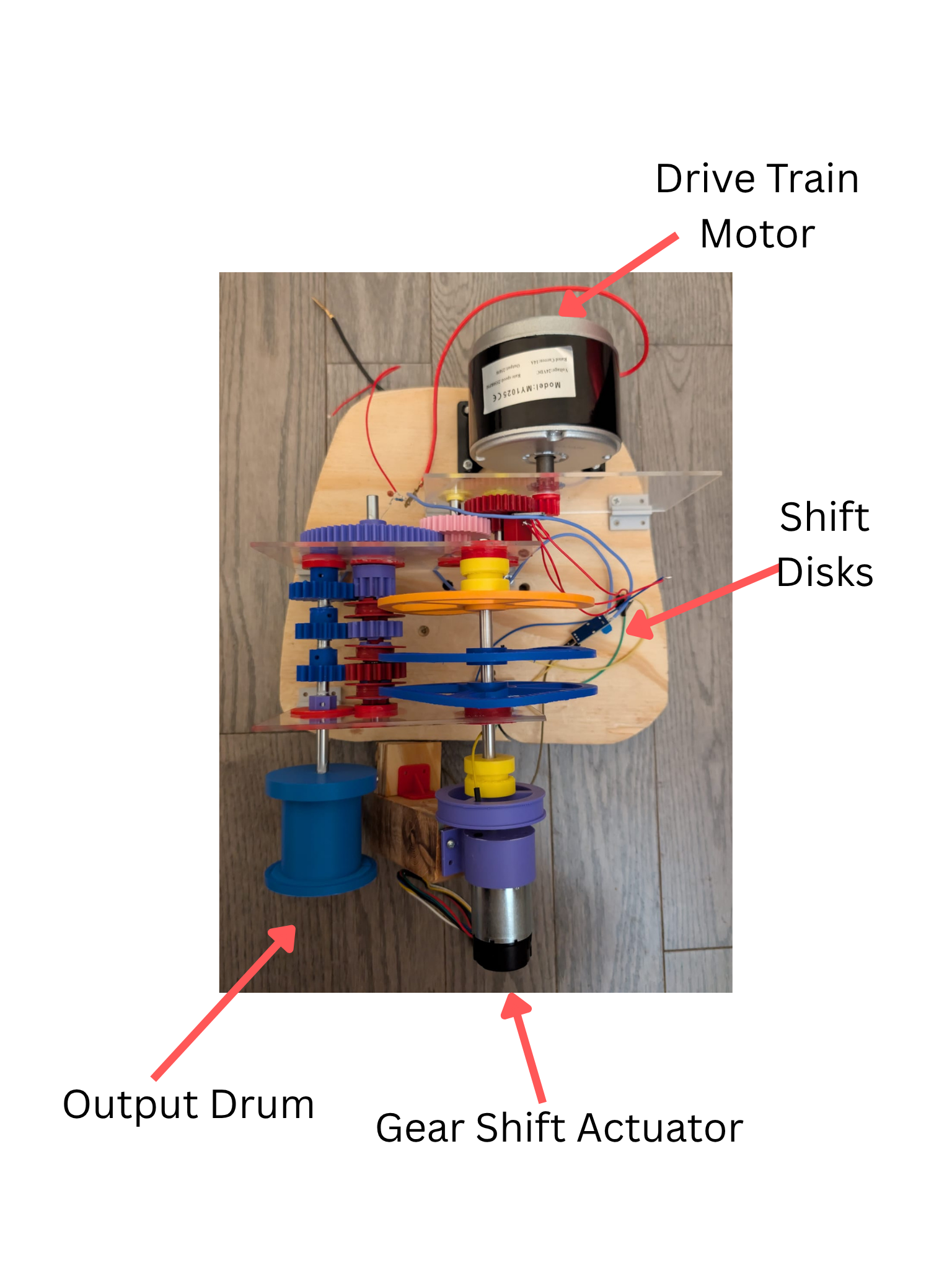
Hardware Demonstration
System Architecture
The firmware partitions work across independent Propeller cogs:
- ADC sensing task samples two RPM channels and motor current.
- Encoder task tracks signed transmission-selector motion.
- Potentiometer task sweeps the drivetrain operating point.
- Main control loop selects gears and refreshes the telemetry display.
The complete platform uses two AS5600 magnetic encoders for motor/output speed, an ACS712 for current, filtered voltage sensing through an ADS1115, and a thermistor for motor temperature. The Propeller coordinates sensing, display output, SD logging, digital-potentiometer commands, and a bidirectional shift motor. Encoder feedback determines when the requested gear displacement has been reached.
Mechanical Drivetrain
A fixed 45:1 primary reduction is followed by three selectable secondary stages:
| Selected stage | Total reduction | Operating intent |
|---|---|---|
| 0.6 | 75:1 | Highest mechanical advantage for loaded, lower-speed operation |
| 1.0 | 45:1 | Intermediate ratio |
| 1.2 | 37.5:1 | Highest output speed with more reflected load inertia |
The interchangeable 3D-printed stages and pulley loading system make it possible to compare how ratio and external load affect acceleration, current draw, output speed, and efficiency.
Automatic Shift Strategy
| Transition | Shift condition |
|---|---|
| Gear 1 → Gear 2 | Motor speed ≥ 600 RPM |
| Gear 2 → Gear 3 | Motor speed ≥ 1,400 RPM |
| Gear 3 → Gear 2 | Motor speed ≤ 1,200 RPM |
| Gear 2 → Gear 1 | Motor speed ≤ 400 RPM |
Using different upshift and downshift thresholds introduces hysteresis, preventing repeated gear changes near a single boundary. Adjacent shifts use calibrated signed encoder displacements; the archived firmware uses 100 ticks per transition.
Sensing and Telemetry
The controller monitors:
- motor-side RPM
- output-side RPM
- motor current
- motor voltage
- motor temperature
- current gear
- shift-motor encoder position
- synchronized SD-card logs
The live composite display reports drivetrain state while synchronized measurements are recorded to CSV for analysis. The archived firmware demonstrates the core RPM acquisition, encoder actuation, threshold-and-hysteresis shift logic, and display pipeline.
Experimental Results
The report and notebooks compare motor voltage, current, motor RPM, output RPM, load condition, transient response, and calculated system efficiency across multiple gear configurations.
Key findings
- The bare motor drew 21.28 W at maximum no-load speed; adding the gearbox increased this to 24.37 W, an approximately 14.5% increase attributed to drivetrain friction.
- The 75:1 configuration moved the motor toward higher-speed, lower-current operating regions under the tested loads.
- Lower total reduction increased the load inertia reflected to the motor and lengthened the modeled acceleration response.
- Efficiency-map overlays provided a data-driven basis for comparing gear operating paths; the archived firmware implements a simpler threshold-and-hysteresis controller.
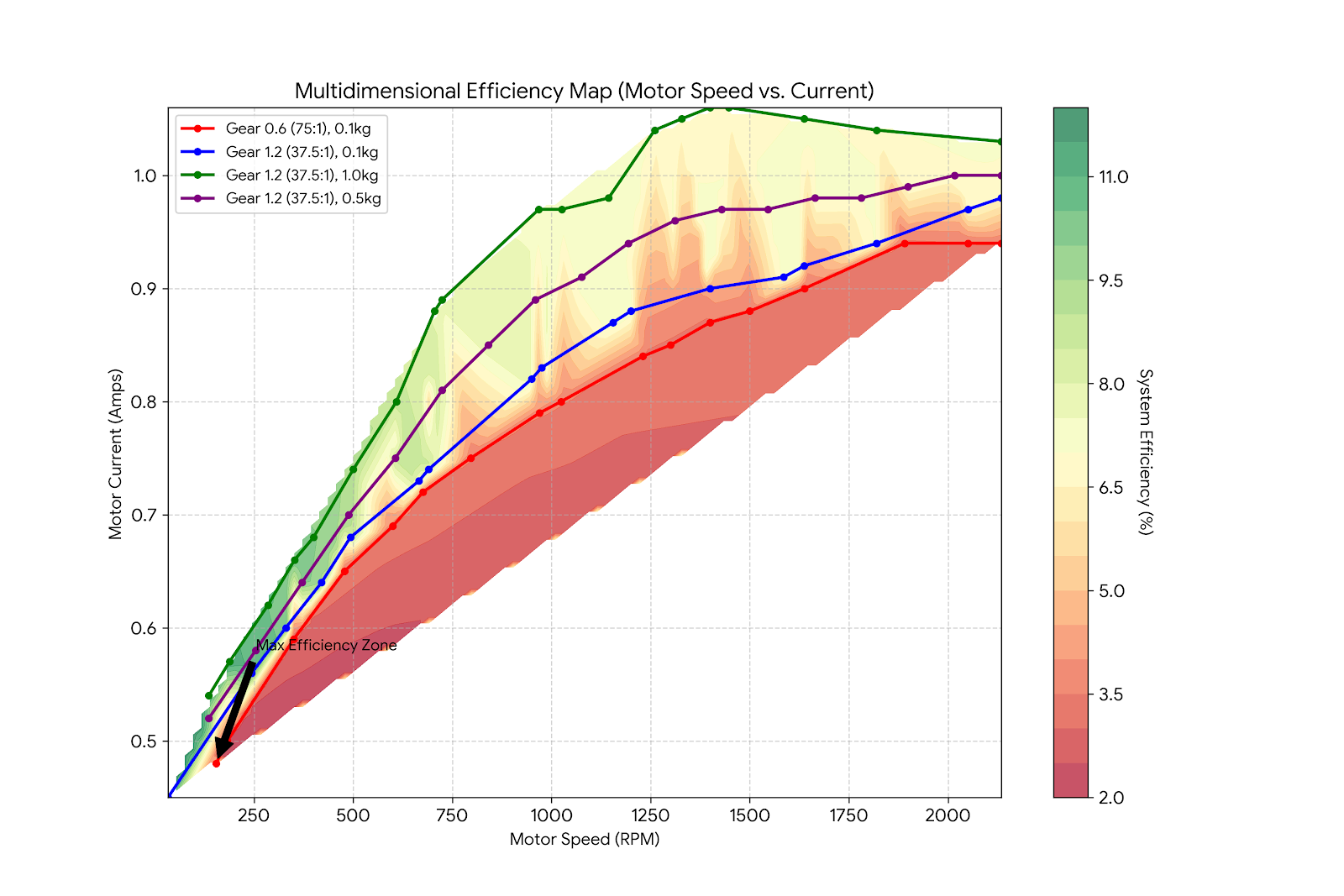
The contour map overlays measured operating paths on motor-speed and current coordinates, showing how gear ratio and load move the drivetrain through different efficiency regions.
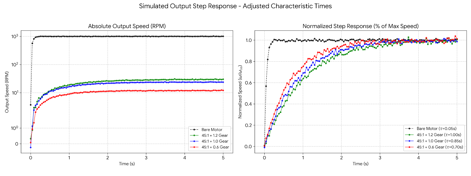
The modeled normalized responses use characteristic times of approximately 0.70 s for 75:1, 0.85 s for 45:1, and 1.00 s for 37.5:1, illustrating the effect of reflected inertia as mechanical advantage decreases.
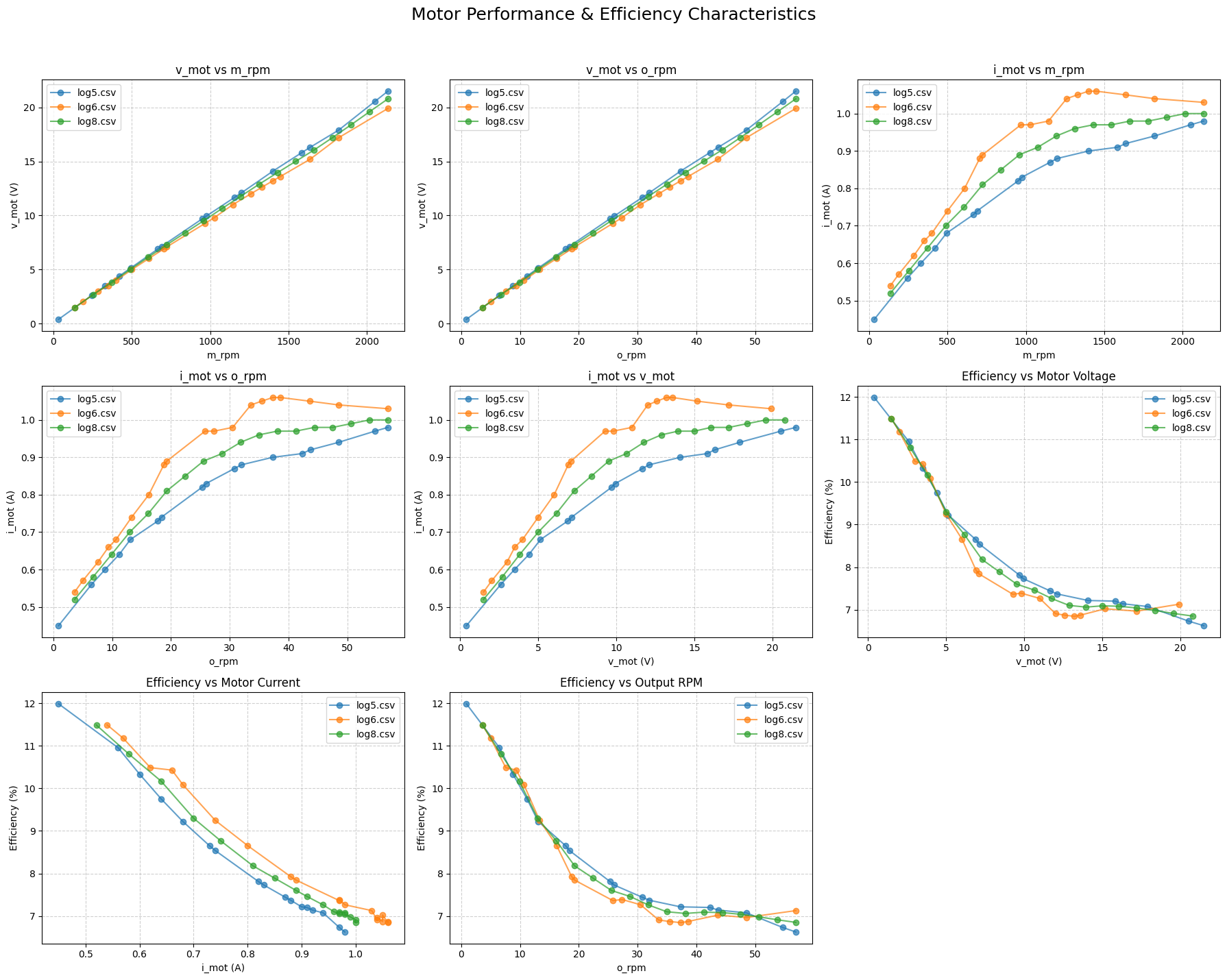
The archived project folder did not contain the raw CSV logs referenced by the notebooks. The public repository therefore retains report figures and notebook outputs as project evidence rather than presenting the analysis as a reproducible package.
Engineering Challenges
Concurrent embedded tasks
- sensing, encoder tracking, potentiometer control, shifting, and display updates must operate without losing speed pulses
- independent Propeller cogs isolate time-sensitive acquisition from the main shift loop
Stable gear selection
- a single RPM threshold can cause gear hunting near the transition point
- distinct upshift and downshift thresholds introduce useful hysteresis
Mechanical shift positioning
- the controller needs repeatable selector displacement despite motor direction changes
- signed encoder ticks provide feedback for adjacent gear movements
Experimental interpretation
- voltage, current, speed, load, and efficiency must be compared across multiple runs
- the notebooks overlay operating paths and generate multi-variable performance plots
Technical Stack
- Propeller C / SimpleIDE
- Parallax Propeller Activity Board
- 24 V / 250 W brushed DC motor
- 3D-printed three-speed transmission
- AS5600 magnetic encoders
- ACS712 current sensing and ADS1115 voltage acquisition
- thermistor temperature sensing
- L298N shift-motor driver and encoder feedback
- X9C104 digital potentiometer control
- SD-card telemetry logging
- multicore embedded task execution
- Python, pandas, NumPy, Matplotlib, and SciPy
- Jupyter notebooks
Limitations and Next Steps
- add shift-motion timeouts and physical limit validation so an actuator fault cannot block indefinitely
- calibrate the RPM conversion against a reference tachometer and document pulses per revolution
- replace fixed encoder displacements with per-gear calibration and fault detection
- snapshot shared sensor state explicitly before control decisions
- restore the raw CSV logs and formalize the efficiency calculation pipeline
- separate hardware drivers, transmission control, and telemetry into testable firmware modules
Continue Exploring
See another system
Interested in the engineering behind this work? I am available to discuss robotics software, embedded systems, autonomy, controls, and robot-learning opportunities.