Closed-Loop Temperature Control (Peltier + TMP117)
Recruiter summary
- Built: A modeled and instrumented thermal enclosure with TMP117 feedback, a discretized compensator, and PWM Peltier actuation.
- Validated: Closed-loop heating from approximately 70 °F toward a 77 °F setpoint and a modeled response approximately twenty times faster than uncompensated behavior.
- Why it matters: Demonstrates the complete controls workflow from plant model and loop shaping to embedded implementation and physical validation.
Overview
Designed and implemented a closed-loop temperature regulation system for a custom acrylic enclosure using Peltier thermoelectric modules and a discrete-time controller derived from continuous-time control theory. The controller was discretized using the Tustin transform and deployed on an embedded microcontroller, enabling stable real-time regulation without relying on a standard PID formulation.
Key contributions
- Modeled enclosure thermal dynamics using a lumped parameter approximation
- Designed a continuous-time compensator and discretized it for embedded execution
- Implemented a real-time discrete-time controller on Arduino Mega
- Integrated PWM-controlled Peltier heating with closed-loop feedback
Physical System
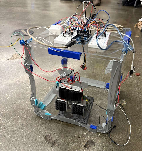
Thermal chamber
- 30 × 30 × 30 cm acrylic enclosure
Actuation
- 4 × Peltier (TEC) modules
- Hot side facing inward, cold side outward
- External heatsinks for heat rejection
- PWM control in heating mode
Sensing
- TMP117 precision temperature sensor suspended at the geometric center (mid-air) to reduce boundary bias
Controller hardware
- Arduino Mega executing the control loop and multiplexing two temperature displays
Control System Architecture
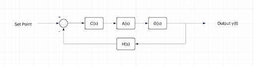
Closed-loop feedback structure:
Control loop
- TMP117 measures enclosure air temperature
- Controller computes control effort at each sample
- PWM drives the Peltier heating modules
- Thermal dynamics produce next temperature state
Thermal System Modeling
Approximated the enclosure as a lumped thermal system with effective resistance and capacitance:
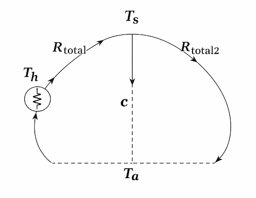
This abstraction captures dominant thermal dynamics while remaining tractable for controller design and embedded implementation.
Controller Design and Discretization
Continuous-time compensator
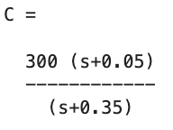
Discretization (Tustin)
Controller discretized using a bilinear transform with a 0.1 s design interval:
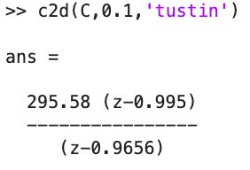
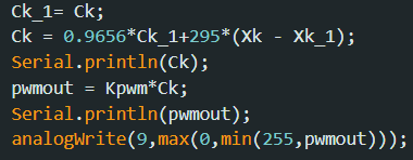
Resulting implemented difference equation:

Embedded Implementation
Controller deployed on Arduino Mega with real-time execution:
- Persistent state for previous control effort and error terms
- PWM saturation to maintain safe actuator bounds
- Potentiometer-adjustable 50–80 °F setpoint
- Dual multiplexed displays for setpoint and measured temperature
Validation and Analysis
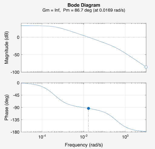
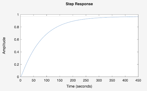
Validated expected closed-loop behavior using frequency and time-domain analysis:
Engineering Challenges and Solutions
Thermal latency and slow dynamics
- Required stability-focused design and smooth control effort
- Addressed via compensator design rather than aggressive gain
Continuous-to-discrete fidelity
- Needed discrete implementation to preserve continuous-time behavior
- Tustin discretization helped maintain stability and response shape
Measurement bias
- Wall and surface temperature bias avoided by suspending sensor at enclosure midpoint
Actuation constraints
- PWM saturation and switching logic implemented to keep control stable and safe
Results
- Deployed a theory-driven controller on embedded hardware
- Demonstrated stable closed-loop regulation architecture using PWM actuation
- Raised the enclosure temperature from approximately 70 °F toward a 77 °F setpoint during experimental validation
- Established an end-to-end workflow from modeling → controller design → discretization → embedded deployment
Technical Stack
- Continuous and discrete-time control systems
- Tustin transform discretization
- Arduino (embedded C++)
- PWM Peltier heating
- Thermal system modeling
- TMP117 sensor integration
Future Improvements
- Add multi-point sensing to measure gradients and validate lumped-model assumptions
- Automate logging/plotting for repeatable evaluation across setpoints
- Benchmark against PID baseline under identical constraints
- Add actuator thermal monitoring and protection
- Add active cooling to reduce overshoot and support bidirectional regulation
Continue Exploring
See another system
Interested in the engineering behind this work? I am available to discuss robotics software, embedded systems, autonomy, controls, and robot-learning opportunities.